Welcome To Spink Controls
-
Call Us
Tubular level Indicator
Manufacturing and Suppliers of Tubular level Indicator
Introduction for Tubular level Indicator
MODEL: SC / L - 001
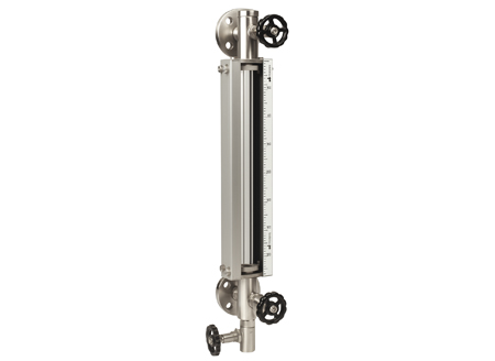
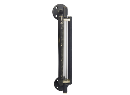
Gauge is fitted between two end fittings through gland packing. The gauge is mounted parallel to tank so as to form a close loop causing tank liquid to seek its level in the gauge. The Gauge Glass is protected with ‘C’ channel. End fitting has built-in isolating valve, drain valve & vent plug.
Auto Ball Check
Auto ball check facility is provided to prevent "liquid loss" from vessel during breakage of gauge glass. It consists of a capsule located within the gauge neck' and contains a 'ball which moves freely along its inner race between the stopper & orifice. During breakage, the pressure on 'ball' from gauge side will be atmospheric, whereas higher pressure from vessel side ("optg pr + liquid column") will cause the ball to move and block the orifice, to minimize liquid loss.
Engineering Specification for Tubular level Indicator :
- Gauge : HW Borosilicate Glass 16 / 19mm OD (25mm for Viscous Liquids)
- End Fitting MOC : CS / SS 304 / SS 316 / PP / PTFE
- End Block Type : W / O Valve / Offset NV with or W / O Auto Ball Check
- Guards : CS / SS304 / FRP C- Channels
- Gland MOC : CI / SS 316 / PP
- Packing : PTFE
- Process conn. : 3/4 ” / 1 ” Flanged (Table D / ANSI 150#) or BSP Screwed
- Vent / Drain : Plug / Ball valve
- Scale : Aluminium Engraved
- CC Dist. : 1500mm in Single Length, Large CCD’s thru’ Coupler
- Visibility : CC Dist – 150mm
- Maximum Temp. : 200°C (Metallic) / 70°C (PP)
- Test Pressure : 10 Kg/cm² (Metallic) / 2 Kg/cm²
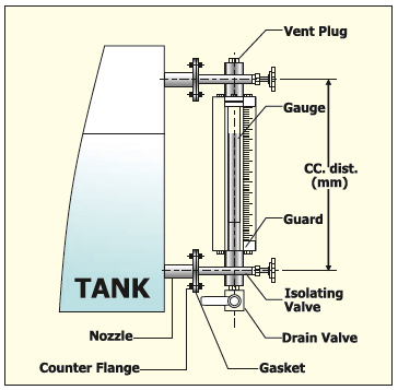
Installation of Tubular level Indicator:
- Side mounted through tank nozzles, having matching counter.
- Flanges / threads, ensuring that CC distance between nozzles.
- Corresponds with CC distance (R) of the gauge.