Welcome To Spink Controls
-
Call Us
Electromagnetic Flowmeter
Manufacturing and Suppliers of Electromagnetic Flowmeter
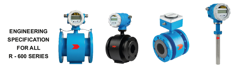
Introduction of Electromagnetic Flowmeter
MODEL: SC / R - 601-e
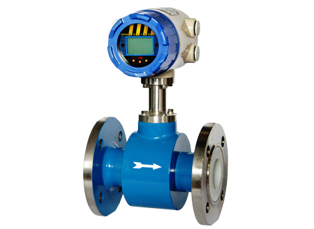
Electromagnetic Flowmeters are based on Faraday's Law of Electromagnetic Induction. In an Electromagnetic Flowmeter, the magnetic field is generated by a set of coils. As the conductive liquid passes through the electromagnetic field, an electric voltage is induced in the liquid which is directly proportional to its velocity. This induced voltage is perpendicular to both, the liquid flow direction and the electromagnetic field direction
Feature :
Spink Electromagnetic flowmeter is designed for measuring and indicating flow & total volume of conductive liquids. As there are no moving parts in the flow profile the device can be used to measure extreme dirty liquids containing solids. The flowmeter is used for conductive liquids only. The flowmeter has been designed for use in all process industries including chemical, water & wastewater.
Flow Chart of Electromagnetic Flowmeter:
| Parameter | SC / R - 601 | SC / R - 602 | SC / R - 603 | SC / R - 604 |
|---|---|---|---|---|
| Nominal dia (mm) | 10 to 3000 | 10 to 200 | 10 to 1000 | 100 to 3000 |
| Working Pressure (Kg/cm2) | 10, 16, 25, 40 | 5 | 16, 16, 25, 40 | 20 |
| Working Temperature | Integral PTFE - 120°C Remote PTFE - 180°C Other - 70°C |
Up to 55°C | PTFE - 120°C Rubber - 55°C |
Up to 120°C |
| Electrode Material | SS316 Std.* | SS316 Std. | SS316 Std. | SS316 Std. |
| Sensor Lining | Std. Rubber | NA | Std. Rubber* | NA |
| Display Version | Integral / Remote | Integral / Remote | Integral / Remote | Integral / Remote |
| Measuring Tube Material | SS 304 Std | HDPE | Se304 Std. | SS316 Std. |
| Sensor Housing Material | Std. CS* | HDPE | Std. CS* | NA |
| End Connection | Flange/Wafer/Tri-clamp/SMS | Flange | Flange/Wafer/Tri-clamp/SMS | NA |
| Flange - Standard | ANSI 150* | ANSI 150* | ANSI 150* | NA |
| Measuring Range | 0.2 to 12 m/sec. Bidirectional | 0.2 to 12 m/sec. Bidirectional | 0.2 to 12 m/sec. Bidirectional | 0.2 to 12 m/sec. Bidirectional |
| Accuracy % | ±0.5%(+0.2 Consult Factory) | ±1% | ±0.5% | ±2% |
| Repeatability | ±0.2% of scan | ±0.2% of scan | ±0.2% of scan | ±0.2% of scan |
| Display | 2 line LCD | 2 line LCD | 4 line LCD | 2 line LCD |
| Display Units | All Standard Engineering Units in m3, Liter, Gallon, ft3, Imperial Gallon | All Standard Engineering Units in m3, Liter, Gallon, ft3, Imperial Gallon | All Standard Engineering Units in m3, Liter, Gallon, ft3, Imperial Gallon, Pressure - kg/cm2 | All Standard Engineering Units in m3, Liter, Gallon, ft3, Imperial Gallon |
| Output | Std. 4 - 20 mA, pulse relay | Std. 4 - 20 mA+, pulse relay | pulse relay | Std. 4 - 20 mA, pulse relay |
| Power Supply | 12 - 60 V AC/DC or 80 - 300 V AC/DC wide supply, Solar Powered |
12 - 60 V AC/DC or 80 - 300 V AC/DC Solar Powered |
Battery Powered 5 Years Battery Life |
12 - 60 V AC/DC or 80 - 300 V AC/DC Solar Powered |
| Protection Class for Sensor | Std. IP 67 Option IP 68 or flow tube in remote type |
Std. IP 67 Option IP 67 / IP 68 for flow tube in remote type |
Std. IP 68 | Std. IP 68 |
| Protection Class for Transmitter | IP 67 / IP 68 | IP 67 | IP 67 / IP 68 | IP 67 |
| Cable Length for Remote | Std. 10 m | Std. 10 m | Std. 10 m | Std. 10 m |
| Installation | Inline flanged type | Inline flanged type | Inline flanged type | Insertion type with use of isolation ball valve Assembly on pipeline. |